|
|
Bob's Shop Notes: |
Click Here for .pdf copy of this article.
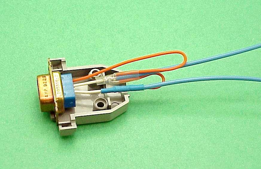
The Task . . .Let's consider mechanics installing and daisy chaining multiple shield pigtails together but before we begin an real installation, consider the kind of backshell (if any) that will be used after it's all wired up Here we see how far the standard d-sub backshell extends behind the connector. Let us suppose I had 14 shielded wires to bring into a 15-pin connector where only one pin was available for shield grounds. Imagine how fat a lump there will be if all the shield terminations are located right next to each other. They would certainly be too big to co-exist INSIDE the backshell. They would make a big, ugly lump in the wire bundle if they ALL existed right outside the backshell. This is why I mentioned earlier that the exposed conductors of your shielded wires may be up to 3" in length. It is no great sin to have up to 3" of your shielded wires "exposed". If I had to put 14 wires into a 15-pin d-sub connector, I would stagger the locations of the pigtail joints such that they were located in groups of 3 or 4 with each group being about 1/2" apart. This keeps them from stacking up the diameter of the wire bundle immediately behind the connector. You can wrap the wire bundle with self-fusing slicone tape to put a nice polish on your handiwork before the backshell is installed. |
|
|
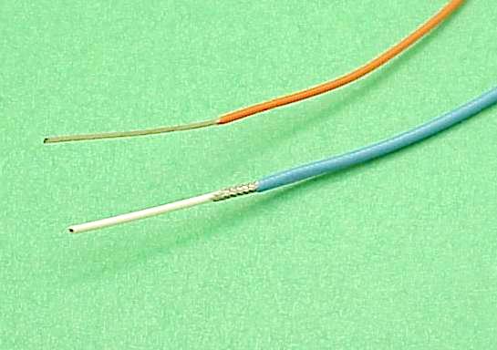
Step 1 . . .Tools needed: (1) A soldering iron with a 1/16 to 3/16" tip . . . wattage not terribly critical but it needs to be hot enough to melt the tip of a strand of solder in one second or so. 40W is certainly enough, many 25W irons will do. We're looking for a 650+ degree iron. (2) Heat gun to finish the joints with heatshrink. (3) Wire cutters and strippers. Materials needed: (1) 63/37 alloy, 0.032" or similar small size solder. I like Kester Resin 44 but there are several good ones. (2) Heat shrink tubing. Solder-Sleeves (optional) more on this product later . . . . Getting Started:Prepare the end of your shielded wire by stripping off the outer jacket to expose 1 to 3" of the shield. Trim back the shield so that only 1/4" extends out from under the shield. The picture here shows about 1" of inner conductor showing . . . this may or may NOT be long enough. More on this later. The goal is make a compact electrical connection to the shield braid with a short piece of small wire. 22AWG is about the largest you want to use, 24 AWG is the smallest. Strip off approx 1" of insulation from from your pigtail stock as shown. |
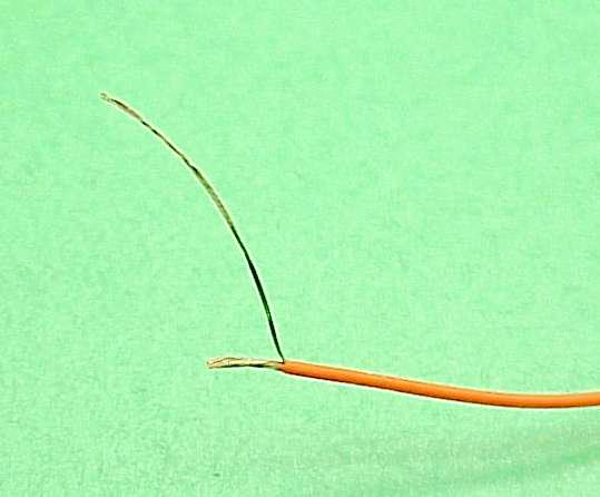
Step 2 . . .Separate out 3 or 4 strands of the pigtail stock . . . unwinding them down to the insulation and bend them aside as shown here. Cut the remaining strands back to 1/4" of exposed wire. |
|
|
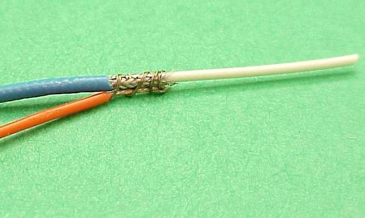
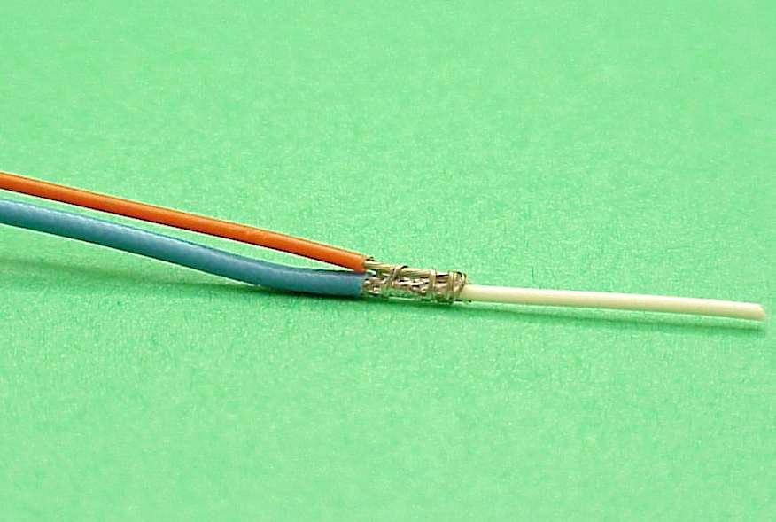
Step 3 . . .Hold the pigtail stock parallel to the shielded wire such that 1/4" of exposed pigtail strands lay right along side 1/4" of exposed shield braid. Wrap the long strands separated out in step 2 around the overlapped conductors to hold them in place for the next step . . . |
Step 4 . . .. . . where we're going to solder the pigtail to the shield braid. Don't see much solder in this picture? That's on purpose. I flow enough solder into the wires to fill the stranding and provide a joint between the pigtail and shield braid but not so much that you increase the overall diameter of the joint. If you think may have more solder in the joint than you need, heat it up to flow the solder and shake off excess solder. Make sure the stuff goes someplace that won't matter. A splash of hot solder in your shoe is an experience to remember . . . the stuff melts nice holes in polyester pants too . . . |
|
|
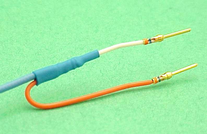
Step 5 . . .Here you see what the finished wires look like after heat shrink has been applied over the shield ground joint and pins are installed on the ends of the wires. Just poke the pins into the connector and this wire is finished . . . UNLESS . . .
|
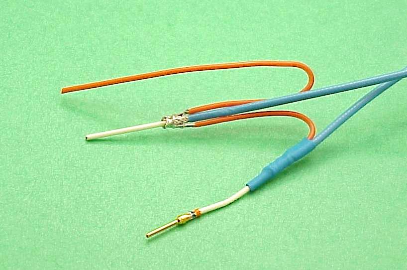
Step 6 . . .You have encountered a situation where the designer of the product expects you to tie of a two or more shield grounds to a single pin in his product's connector! Okay, no big deal. Instead of crimping a pin on the first shield's pigtail, strip off 1/4" of the far end and solder it into the pigtail joint for the next wire as I've done here.
|
|
|
Step 7 . . .You can continue this daisy-chaining of shield grounds to a single pigtail wire for as many shields as necessary. Here's what a pair of shielded wires looks like when you're ready to poke the pins into the connector.
|
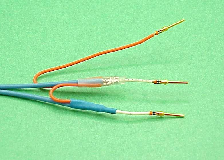
Step 8 . . .There is an alternative technology you might consider. Raychem corporation makes a product called "solder sleeves". These are a high temperature heat-shrink tubing with a ring of sealant (the blue bands at each end of the sleeve) and a ring of solder in the middle (the silver band). You can get these with and without a pre-fabricated pigtail. The ones I used here came with a pigtail. You install them with a heat gun that shrinks the tubing, melts the solder to effect a connection between shield and the pigtail, and melts the sealant material to close off both ends of the sleeve. Nifty but not cheap.
Here I have daisy chained three shields together onto a single ground lead using solder sleeves. The solder sleeves make for a slightly more compact joint than the one I've illustrated.
|


|
 Click here to contact Bob at AeroElectric Connection Click here to contact Bob at AeroElectric Connection |